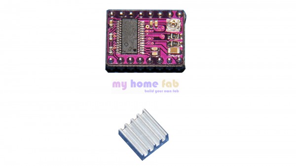
Here you find the technical description of our stepper motor driver board with the DRV8825 circuit. Our board is pin compatible with the Polulu driver board and can be used on standard RepRap controller boards like RAMPS 1.4 or RUMBA.
The board is able to drive stepper motors with a phase current up to 2.2A. To run the driver board with high currents a heatsink must be assembled on the driver circuit. Also a fan must be assembled nearby the driver board to ensure a sufficient cooling. The motor current is adjusted with the poti visible on the upper right corner on the picture you see below.
Mit diesem Treiberboard können Schrittmotoren mit einem Strom von bis zu 2,2A angesteuert werden. Dazu muss jedoch ein Kühlkörper auf dem Chip montiert werden und die Platine im Betrieb mit einem Lüfter zusätzlich gekühlt werden. Die Einstellung des Stroms erfolgt über ein Trimmpoti, im Bild in der oberen rechten Ecke zu sehen. Dieses Board mit dem Treiber DRV8825 ist eine Weiterentwicklung der weit verbreitetend Polulu Schrittmotorplatine mit dem DRV4988 Chips und ist pinkompatibel zu diesen Boards. The pinout of the board is the same as for the A4988 drivers, so it can substitute directly A4988 drivers.
The advantages of the DRV8825 are a higher motor current output and a microstepping up to 1/32 step.

This board has the following characteristics:
- a configurable microstepping of full step, half step, 1/4 step, 1/8 step, 1/16 step and 1/32 step
- an adjustable motor phase current, which allows a higher supply voltage than the rated voltage of the stepper motor
- a protection against oveheating, overcurrent and shut off on low voltage
- the stepper motor can be driven with voltages up to 45V
The part is delivered with a double sided adhesive thermal pad and a heatsink. The pin strip is already soldered, so you only have to assemble the heatsink with the termal pad. The following picture shows the driver board with the assembled thermal pad.

The next picture shows the driver board with the assembled heatsink.

Configuring the micro stepping
| MODE0 | MODE1 | MODE2 | Microstepping |
| 0 | 0 | 0 | Full step |
| 1 | 0 | 0 | Half step |
| 0 | 1 | 0 | 1/4 step |
| 1 | 1 | 0 | 1/8 step |
| 0 | 0 | 1 | 1/16 step |
| 1 | 1 | 1 | 1/32 step |
The next picture shows the configuring of the micro stepping on the RAMPS 1.4 extension board. The micro stepping for the stepper motor is adjusted with the jumpers within the yellow rectangle. Setting the jumper equals a "1". Removing the jumper equals "0".

The next picture shows the assembled driver board for the X-axis of the 3d printer. Please notice that the alignment of the trim poti related to the RAMPS 1.4 is opposite to that of the A4988 driver!


