One of the importent topics when setting up a RepRap 3d printer, is the adjustment of the current driving the stepper motors. One of the common aproaches is tune the current with the poti on the driver board until the motor moves sufficiently. And it works without overheading or missing steps.
But there's also a second way well known by measure the reference voltage of the driver circuit. The driver circuit adjusts automatically the motor current based on voltage at the reference input.
Pololu describes on their website, that the relationship between the stepper motor current and reference voltage is expressed with the following equation:
Imot = 2 * Uref
That means, if the DRV8825 shall drive the stepper motor with e.g. 1.4A the reference voltage has to be adjusted to 0.7V.
This equation is only true, if the resistant fo the current sensor has a value of 100mOhm, as our driver boards do!
But where you have to measure the reference voltage Uref on the DRV8825?!
Here's the answer:
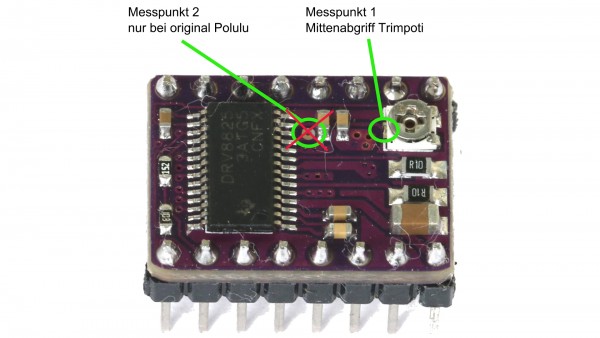
The original Pololu layout offers two possibilities for measuring the reference voltage:
- at the center tap of the poti where you tune the motor current (called "Messpunkt 1" in the picture below)
- at the reference measuring point on the board (called "Messpunkt 2" in the picture below)
On our board you can measure the reference voltage only at "Messpunkt 1", the center tap of the poti!

There exists also a second driver board layout for the DRV8825. It's designed bei Kliment. These driver boards also offer to points for measuring the reference voltage as you can see in the picture below:

The adjustment of the stepper motor current will be done in three steps:
- Identify the maximum current of your stepper motor from the datasheet
- measure the reference voltage at the center tap and tune it with turning the poti, note: the motor won't be connected yet!
- connect the stepper motor with the controller board and check function by moving the axis


